
1. Before installation
This guide applies to the SX70 K board and is based on the Chinese source manual 202603 V1.6.
- Before replacing the mainboard, confirm that the camera can trigger its flash and identify the appropriate flash wiring method. See Chapter 3.
- Take electrostatic discharge precautions; anti-static gloves are recommended.
- On Original (O) cameras and other models with an aluminum camera head, pay attention to electrical insulation and the light sensor position before installing the board.
Modification risk: The source manual states that board damage caused by soldering or accidental short circuits is not covered by warranty. If wiring or model details are unclear, consult the manufacturer rather than guessing.
The WeChat mini program code is shown below. For connection, shooting, and firmware update instructions, see the Mini Program User Manual V1.8.

2. Product functions
- Supports Original (O), Alpha, Model, and Sonar cameras.
- Supports switching between 600 and SX-70 film modes.
- Displays automatic metering results and supports timed shooting.
- Offers automatic metering and A / T / B shooting modes, with selectable shutter speeds from 25 seconds to 1/8000 second.
- Supports WeChat mini program control on Android and iOS.
- Supports firmware updates and double exposure.
The electronic frog tongue function is configured under Advanced settings → Ejection mode (高级配置 → 吐片模式). The source specifies availability from board version 1.1.8:
| Mode | Behavior |
|---|---|
| Automatic ejection (自动吐片), default | Keep holding the physical shutter button after pressing it. Film stays inside after the exposure until you release the button. |
| Second-press ejection (二次快门吐片) | Film is not ejected when you release the button after shooting. Press the shutter a second time to eject; there is no need to keep holding it. |
| Immediate ejection (立马吐片) | Similar to the original factory ejection behavior. |
These are the K-board V1.6 source instructions for the physical shutter button. Mini program screens and available functions may vary with firmware. Refer to the mini program manual for current interface instructions.
3. Wiring
For Sonar autofocus cameras, reconnect the wiring according to the original factory mainboard. Leave the three sonar indicator wires at the upper-left corner of the board disconnected; reconnect the remaining wires as on the original board. Consult the manufacturer if anything is unclear.
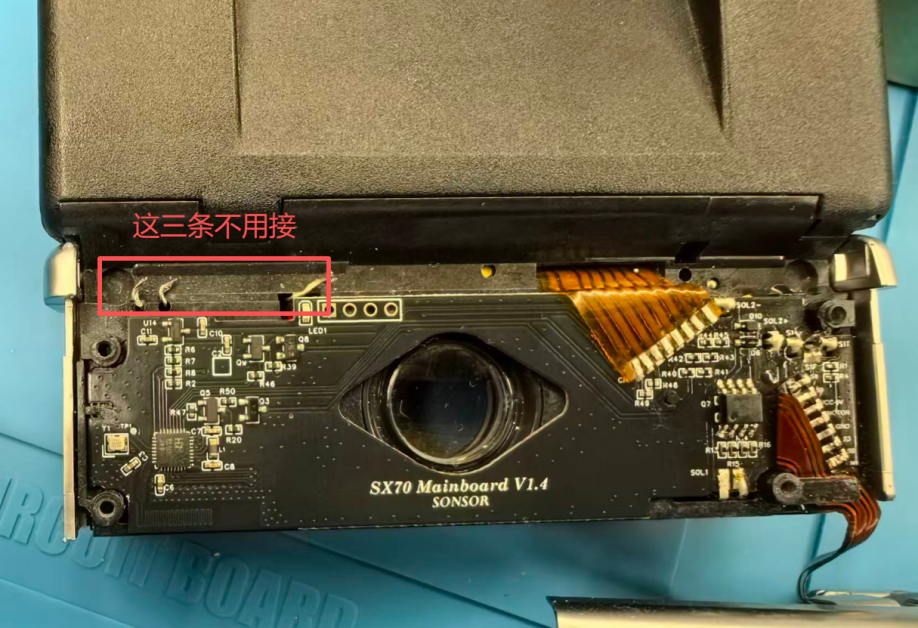
For manual-focus cameras, follow the instructions below.
3.1 Flash interface wiring
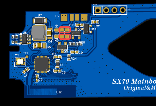
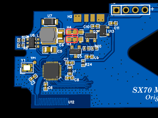
Step 1: Basic wiring. Wire the board as shown in Figure 3-2. Red wires are required; blue wires are optional as needed.
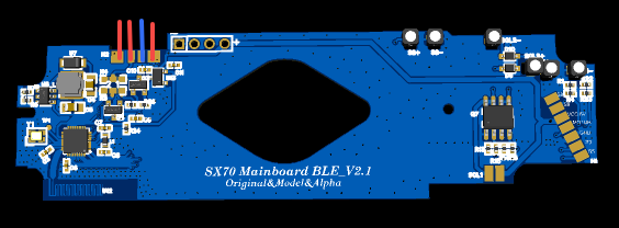
Step 2: Identify the flash driver board type. SX-70 flash driver boards come in several versions, so identify the wiring type first.
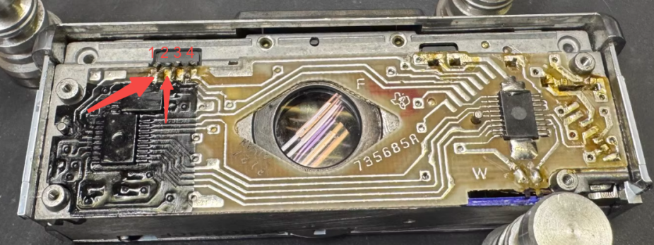
Perform this test with the original mainboard still unmodified. Short only the two pins marked “1” and “2” in Figure 3-3, not arbitrary contacts.
Insert the flash, wait until charging is complete, then use tweezers to short the two left-hand pins marked “1” and “2” in Figure 3-3:
- If the flash fires, use method 1 (Figure 3-4).
- If the flash does not fire, use method 2 (Figure 3-5).
3.2 Solenoid wiring
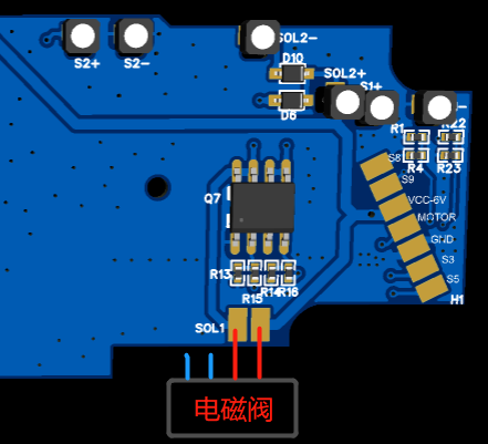
Connect only the red wires shown in Figure 3-6. The blue wiring is not required.
A four-pin solenoid must be converted to two pins. Disconnect the internal diode by desoldering one of its leads.
4. ND filter replacement
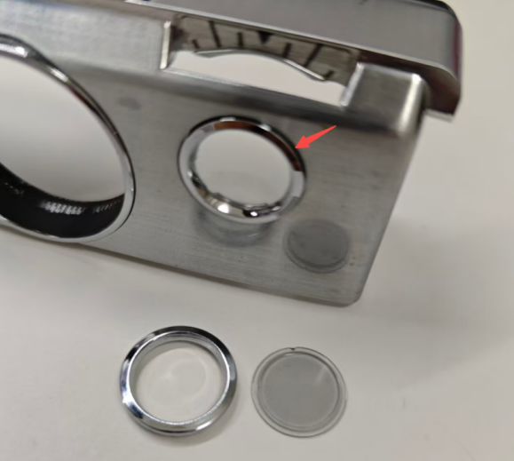
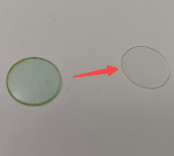
- Gently lift and remove the original ND filter with tweezers. See its position in Figure 4-1.
- Peel the protective film off the new filter, as shown in Figure 4-2.
- Fit the new filter into position to complete the replacement.
5. Shutter speed calibration
Aging shutter solenoids and other mechanical components can cause shutter timing errors, resulting in overexposure or underexposure. One parameter set cannot suit every camera, so keyframe calibration is provided for high shutter speeds to adjust the shutter opening.
The source states that calibration can theoretically improve results as long as the camera operates normally. Calibration is not a substitute for repairing mechanical faults.
Set a fixed shutter speed in the mini program, such as 1/2000 second or 1/500 second, and film the shutter blades using your phone’s slow-motion mode at 240 fps or higher.
5.1 Enter test mode
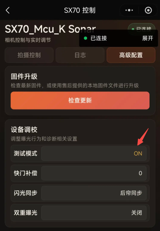
Open Advanced settings (高级配置) and set Test mode (测试模式) to ON. The mirror will not rise; only the shutter blades move, making the opening easier to observe.
5.2 Set up the test environment
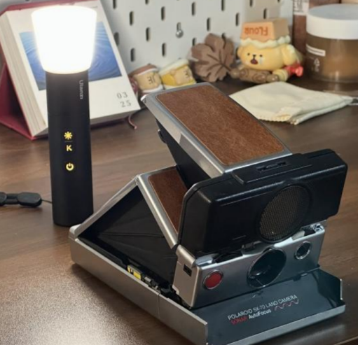
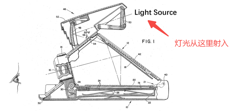
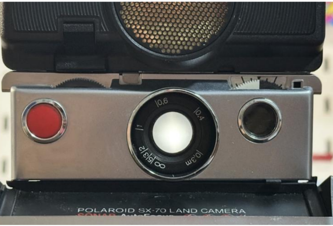
Turn on the light, direct it into the camera as shown in Figure 5-2, and observe the shutter blades from the front.
5.3 Calibrate the shutter
Step 1: Observe the opening. Select Manual mode (手动模式), operate the relevant shutter speed, and observe the opening.
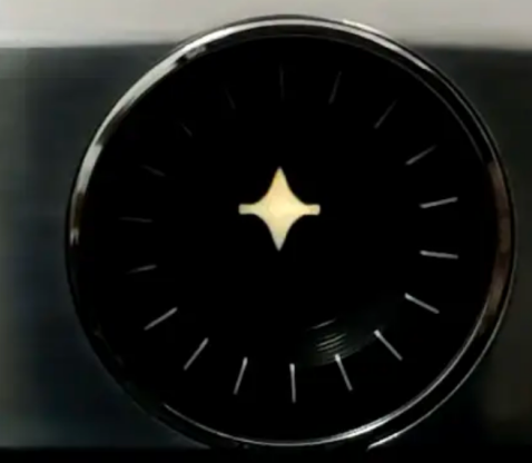
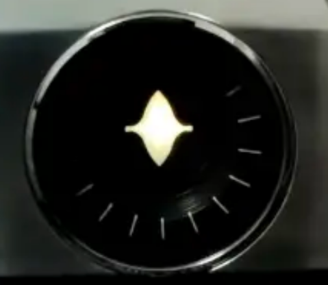
Step 2: Adjust compensation. The two parameters have different scopes:
| Parameter | Scope | Range and step |
|---|---|---|
| Shutter compensation (快门补偿) | The entire shutter-speed range | -13 to +13, in steps of 1 unit |
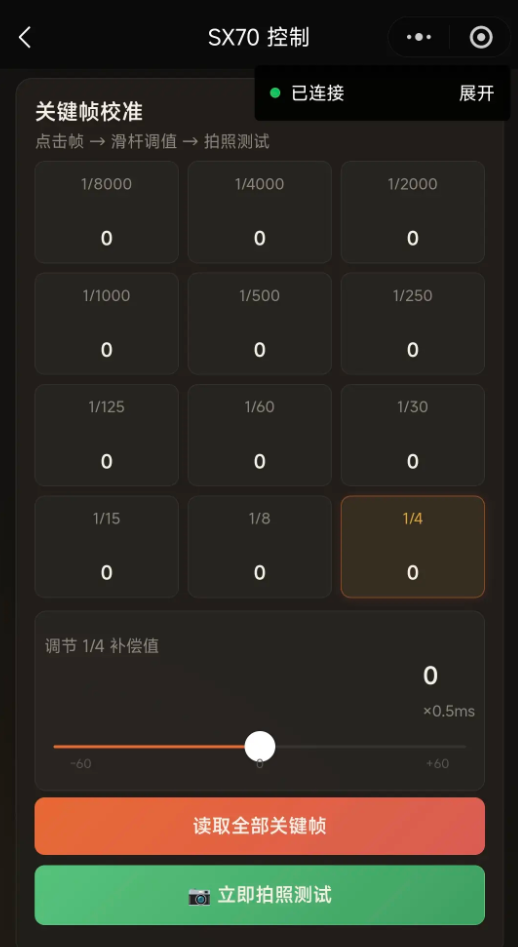
| Keyframe calibration compensation (关键帧校准补偿值) | The selected speed and neighboring 1/2-stop or 1/3-stop speeds | -60 to +60, in steps of 0.5 units |
For example, after setting compensation for 1/8000 second, the values for 1/6400 and 1/5000 second are calculated linearly. Positive values increase time and allow a larger opening; negative values shorten time and make the opening smaller.
Start at 1/8000 second, then 1/4000 second, working progressively toward slower speeds. Adjust 1/8000 second using Shutter compensation; adjust the subsequent speeds with their respective keyframe compensation values.
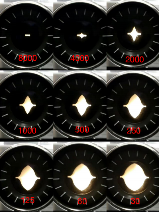
Select the relevant keyframe, then tap Test shot now (立马拍照测试) to verify. Figure 5-6 shows reference openings from 1/8000 to 1/30 second.
6. Flash mode verification
After confirming that the flash fires, switch off the flash power, manually set the focus distance to its closest setting, and press the shutter.
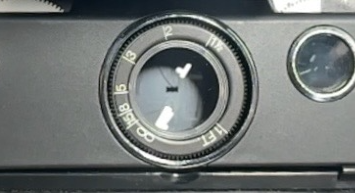
If the shutter opening matches Figure 6-1, the cut-off mechanism described in the source manual is working normally.
7. Frequently asked questions
Can I use a battery adapter or external power unit after installing the board?
A battery adapter (电屁股) is supported. An external power unit (电脑袋) depends on support from its manufacturer.
How do I switch film modes?
Set the film mode directly in the mini program.
Does dual-mode switching require a hardware modification?
Mode switching is implemented in software; no additional hardware selector switch is needed. This refers to mode switching itself, not to the physical work required to install the mainboard.
Is Bluetooth supported?
Yes, through the Bluetooth mini program. Contact the seller to obtain it. See the mini program manual for connection instructions.
How do I identify the correct flash trigger method?
First identify the type on the original board as described in Section 3.1. The source FAQ adds: try method 1, then method 2 if the flash does not fire. If neither works, the flash module may be faulty. Consult the manufacturer if the wiring is unclear.
Why does the opening vary at the same shutter speed during calibration?
This may be a mechanical issue, particularly noticeable at high speeds. Aging mechanisms or an unclean solenoid interior can cause inconsistent opening sizes.
Which flashes are supported?
The source describes support for commercially available electronic flashes, but not original disposable flashbars. Confirm individual models or special requirements with the developer.
What if the mini program cannot find the Bluetooth device?
The V1.6 source says Android generally prompts you to enable access, while iOS requires Bluetooth and location services to be enabled for scanning. Permission prompts may differ by OS version. Also consult the V1.8 connection instructions and check your current system permissions.